| 01 | Mount Geometry
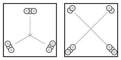
After deciding on the mount geometry, download the applicable CAD models (IGS) and then either the interface library features (Solidworks) or interface examples (IGS). For three-legged mounts, only use 2-DOF ("V") mating elements, oriented toward the common center. For four-legged mounts, only use 1-DOF ("D") mating elements, oriented as explained in our technology section. Contact us with any questions |
|
| 02 | Interface Features
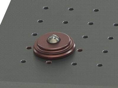
Each mating element comprizes a bottom component (single ball) and a top component (either a BiCollar or a UniCollar). Optionally, a retainer assembly can be added. |
|
| 03 | Bottom Component
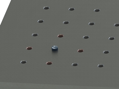
Choose the locations for the mating elements. Whether a three-legged or four-legged mount, the mating elements should describe as large a shape (triangle or quadrangle) as possible. |
|
| 04 | Top Component
Each location should have its four adjacent grid points vacant, as those will be later used by the clamp plate screws. Place a centering screw (provided) in each location, and hand tighten. Do this for both the bottom (optical table) and top (bottom side of breadboard), and make sure their positions match. |
 |
| 05 | Retainer
Select a “pivot point” near the common center of the mating elements (the same point on both the optical table and the breadboard). It is convenient to mark the two pivots with standard screws. |
 |
| 06 | Load Considerations
Place the bottom mating components (the ones without the two collar elements) on the centering screws, making sure they are seated flush on the optical table. The components do not have a preferred orientation. |
 |
| 650-605-4500 | Specification subject to change without notice ©2017 g2-engineering |