| 01 | Identify Components
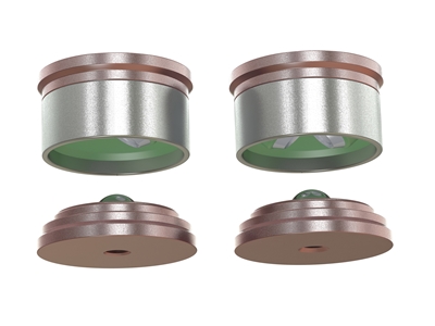
Identify the mating components. In a three-legged mount there are three 2-DOF (“V”) mating elements. In a four-legged mount there are two 2-DOF (“V”) mating elements and two 1-DOF (“D”) mating elements. Each element comprises a bottom component that attaches to the optical table and a top component that attaches to the underside of the breadboard. The top mating component is the one that contains the two collars, protected by an external tube. |
 |
| 02 | Choose Locations
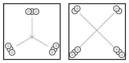
Choose the locations for the mating elements. Whether a three-legged or four-legged mount, the mating elements should describe as large a shape (triangle or quadrangle) as possible. In a three-legged mount, the c.g. must remain within the triangle described by the three mating elements. In a four-legged mount, the c.g. must remain inside the rectangle described by the four mating elements, and also remain about 25% of an edge's length away from the two 1-DOF corners. |
 |
| 03 | Centering Screws
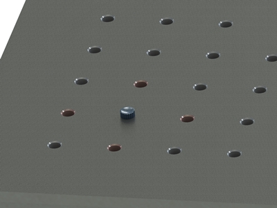
Each location should have its four adjacent grid points vacant, as those will be later used by the clamp plate screws. Place a centering screw (provided) in each location, and hand tighten. Do this for both the bottom (optical table) and top (bottom side of breadboard), and make sure their positions match. |
 |
| 04 | Pivot Point
Select a “pivot point” near the common center of the mating elements (the same point on both the optical table and the breadboard). It is convenient to mark the two pivots with standard screws. |
 |
| 05 | Bottom Components
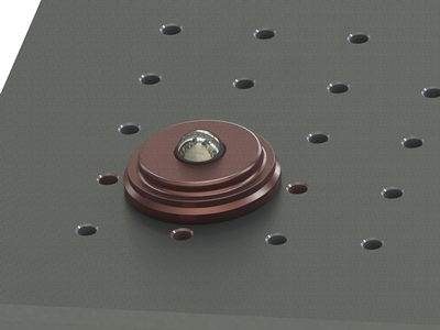
Place the bottom mating components (the ones without the two collar elements) on the centering screws, making sure they are seated flush on the optical table. The components do not have a preferred orientation. |
 |
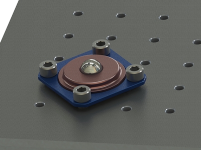
| 06 | Bottom Clamps
Place the blue clamp plates on the bottom mating components, so that the conical surfaces match. Hand tighten the clamp plate screws and make sure the clamp plate does not tilt. Finish tightening with a wrench while following a cross-pattern so that the clamp plate remains flat. The maximum torque that can be applied depends on the specification of the optical table. |
 |
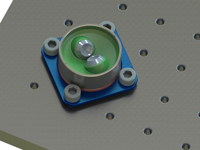
| 07 | Top Components
Place the top mating components on the centering screws. Place the blue clamp plates on the bottom mating components, so that the conical surfaces match. Hand tighten the clamp plate screws and back out a quarter turn. The top components have to be clocked correctly - align the sight notches at the end of the outer tube with your pivot point. Finish tightening as in step 5 above. |
 |
| 08 | Check assembly
Place the breadboard on the optical table, and confirm that all mating elements match and engage properly. The tube that protects the two collars should have a clearance of about 1 mm. |
|
| 09 | Locate Retainers
Identify locations for the retaining screws one near each “V” mating element (preferably in one of the four spots diagonally from its centering screw), and one approximately halfway between the “D” elements. |
|
| 10 | Install Retainers
Place the threaded insert in the optical table, and insert the retainer screw through the matching thread in the breadboard. Hand tighten till the spring flattens, then back out one turn. Remember that the OTx mount system is designed only for stable horizontal static assemblies. The retainer bolts only provide a second line of defense to secure the breadboard and mitigate an accidental bump, but should not be relied on as a primary load carrier. |
|
| 650-605-4500 | Specification subject to change without notice ©2017 g2-engineering |