|
Takeaway points
|
Ruggedized Kinematic Mounts
As explained here, a simple 3-groove kinematic mount is constructed using three spherical protrusions, each located inside a V-groove, contacting each of its side walls at a single point. For the mount to function, it is imperative that the spheres be able to travel freely along the axis of the V-groove. If the motion is impeded, the spheres will come to rest in an off-nominal position, the assembly will retain some internal stresses, and repeatability will be diminished. The problem with traditional kinematic mounts is that the point contact between the sphere and the wall of the V-groove causes a "dimple" to form in the wall, and "dragging the dimple" along the axis of the groove creates exaggerated friction. Additionally, under moderate loads (20 kg for 1" hardened steel components") the dimple become a permanent deformation. Once this occurs, the groove gains a "preferred location" for the sphere to settle into, and the functionality of the mount is ruined. 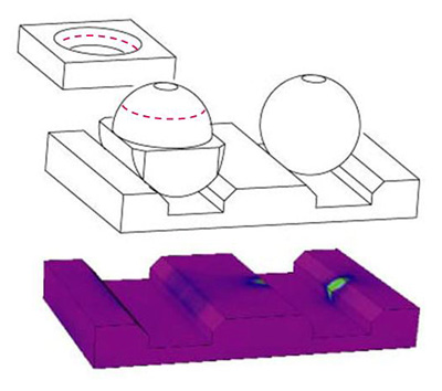
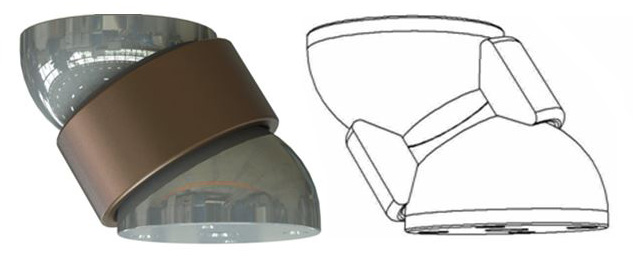
Spherlinder mating element
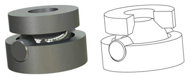
Our first product (The Spherolinder, shown on left) emulates a sphere-in-V mating element, but does so using only line contacts, and so is much more sturdy. Line contacts are still Hertzian contacts, in that the initial contact has zero area and increases in a predictable way due to the bulk geometry of the parts, and they retain the same radius of curvature as the spheres used in the classic mount. The line contact can carry approximately 100x as much load as an equivalent point contact before incurring damage, and retains most other properties of the point contact such as resistance to film (grease) contamination. In fact, since the elastic deformation of the Hertzian contact (in the order of a few um) is higher than the geometric abbertions in the fabrication of the components of the mount, precision is further enhanced due to elastic averaging the occurs along the line of contact. For this reason, repeatability is actually further enhanced as load is increased. Our follow-on products perform a similar function, but on a wider variety of mating geometries, and using either spheres contacting cones, or cylinders contacting V-grooves. Concept geometries for mating elements that constrain 1, 2, and 3 degrees of freedom (DoFs) are shown below. (3-legged mounts use exclusively 2-DoF mating elements. 4-legged mounts can use combinations of 1, 2 and 3 DoF mating elements.)
The operation of line contacts is demonstrated in the video below. Educational Demo Kit
|
 1-DoF ("Collar")
 2-DoF ("Bead")
 3-DoF ("Cone")
| 650-605-4500 | ©2017 g2-engineering |