|
Takeaway points
|
Kinematic Mounts 101
It is easiest to illustrate kinematicity by way of a two-dimensional example, in which a beam (purple) is attached to the factory floor using two mating elements (Orange). 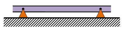
Over-constrained. The two pin joints "fight each other" over the horizontal positioning of the beam.
In the simplest configuration, the two mating elements are pin joints that are rigidly attached to the floor. Each pin joint determines the position of its end of the beam in X and Y, but allows the beam to rotate (theta). Overall, therefore, the two mating elements together constrain 2+2=4 degrees of freedom, while the beam (in the plane) has only 3 degrees of freedom. Since 4>3, this situation is over constrained. The practical implications in this case are:
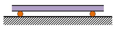
Under-constrained. The beam can still move in the horizontal direction.
In a second configuration the two mating elements are roller pins. Each roller pin only determines the position of its end of the beam in the Y direction, and allows the beam to move freely in the X direction and to rotate in the plane. Overall, the two mating elements now constrain only 1+1=2 degrees of freedom, while the beam still has 3 degrees of freedom in the plane, Since 2<3, this situation is under-constrained. The practical implications in this case are quite simple: The the beam is not supported in the X direction and so can move freely - its position is not known, and it cannot exert any counter-forces in that direction. 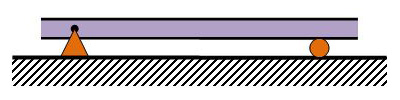
Well-constrained. 3 constrains for 3 degrees-of-freedom (X-Y-θ)
The kinematic mount aims to have exctly 3 constrains for the 3 degrees of freedom. We do this here by using one pin joint mating element (constraining two degrees of freemdom), and one roller pin mating element (constraining only one). overall, exactly 2+1=3 degrees of freedom are constrained, and so the set of equations governing the beam is well posed. The benefits of such a mount are:
Similar reasoning can be applied in the 3D world of solid objects, where there are a total of 6 degrees of freedom for each body (Motion along the X,Y and Z axes, and rotation about each of them). Kinematic solutions in 3D exist, and include (among many) the cone-v-flat mount and the 3-groove mount. Both of these mounts are kinematic, since they constrain a total of exactly 6 degrees of freedom. The Three Groove Mount is more elegant, it is symmetrical, and it is the basis for our family of three-legged kinematic mounts.
The products we offer are used to create 3-D kinematic mounts, while also addressing issues such as fragility and low load-carrying capcity that are usually inherent to kinematic mount designs. For more information, see our technology pages. | ||||||
| 650-605-4500 | ©2017 g2-engineering |