|
Takeaway points
- 100x the capacity of a sphere of equal radius. Ton-level loads, µm-level repeatability.
- All mounts are ruggedized by eliminating point contacts in favor of line contacts.
- Kinematically equivalent to 3-spheres-in-groove mounts.
- The direction of the line contact reduced friction and stiction, so repeatability and stress-reduction are enhanced.
|
Frequently Asked Questions
You require that that the cylindrical and spherical mating features be (respectively) "exactly" cylindrical, spherical, and concentric - doesn't that make the mount non-kinematic?
Any deviation of the actual physical shape of the mating surfaces from their abstract geometrical description always matters of course - whether the bodies are spheres, cones, cylinders, v-grooves, Spheroilnders or Beads. However, there are several factors that work in our advantage:
First, it is always easier to fabricate a single solid body to µm accuracy than it is to locate the mating elements to that tolerance. Therefore we can allow mm-level deviations in the location of the mating features, while using µm-precise mating elements.
(The same logic applies when considering deformations caused by thermal expansion or mechanical stress. A cm-scale mating element will experience only 1% of the deformation of a m-scale assembly, and additionally will have temperature uniformity more than 100 times smaller.)
Second, certain aspects of the mating pair (for example the very limited rotational range of motion of the Spherolinder or Bead) reduce the propegation of certain fabrication deviations such as eccentricity.
Finally, since the expected elastic deformation of the line contacts is in the 10 µm range, it swamps and averages out any localised µm-level deviations - which manifest themselves as non-uniform stress along the line of contact, but not as automatic 1:1 positioning errors.
Since the "Collar" mating elements are tilted with respect to the plane of the mount, it introduces stresses in the mated components. Isn't this a non-kinematic behavior?
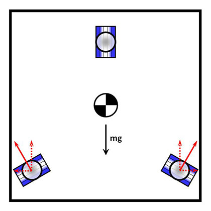
As a matter of fact, all kinematic mount elements generally communicate through in-plane stresses. Take for example the classic 3-groove mount, when used in a vertical (wall-mounted) orientation (shown on the right). Clearly, the vertically-oriented groove cannot take vertical forces, and the two slanted grooves create normal forces that have perpendicular components (horizontal dashed arrows) that put the mated component in tension - and so also create the same type of in-plane stresses.
What is true, however, is that if we ignore the weight of the mated components, and only consider clamping forces that go through the mating element, then no stresses are caused in the mated component. This is also true for 4-legged mounts, as long as the clamping forces are applied in the respective axial directions of the mating elements.
The difference is that in a 3-legged mount the axial directions of all three mating elements are parallel to each other, and so in the case of a horizontal static load they also conincide with the gravity vector - which is impossible in a 4-legged mount. However, in almost all designs, there are load cases (e.g. tip-tilt, dynamic or seismic loads, accidental nudging) that will cause the load vector to shift, and so stresses in the mated components will occur anyway.
The important property is that such stresses are not caused by position mismatch of the mating elements, or by thermal expansion - they are simple mass distributions, and are not caused by over-constrains.
There are kinematic mounts with even more than 4 legs - such as hexapods! Why is 4 legs so special?
That is completely true - a 4-legged mount is not a record, though typically hexapods are arranged in a triangular pattern and so are less suitable for rectangular bodies. Also, most hexapods are not built as kinematic mounts that can be mated using motion along one axis.
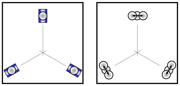
In fact, it is possible to construct a hexagonal mount using 6 collar-type mating elements, by replacing each bead with a pair of collars.
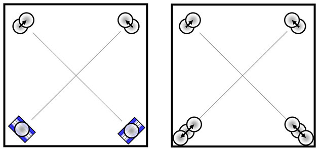
Doing so to a 3-legged mount (top figure) results in a more or less standard hexagpod (though detachable), and doing so to a 4-legged mount (bottom figure) results in a very assymetrical detachable hexapod, that is indeed suitable for use with rectangular objects.
What happens if one side of a kinematic mount undergoes thermal expansion while under load.
Rigidity, static friction, stepwise motion
|